Friday, March 11, 2011

Sejarah Migas Indonesia


     Minyak Bumi pertama kali ditemukan di Timur tengah (Parsi kuno/Iran) yang ditemukan sebagai rembesan yang muncul kepermukaan dan diperkirakan bahwa Nabi Nuh adalah orang yang pernah menggunakan minyak bumi ini untuk menambal perahunya agar tidak kemasukan air, dimana minyak bumi yang dipergunakan berbentuk Asphalt atau Teer.

     Pada zaman berikutnya juga ditemukan gas bumi yang muncul ke permukaan dan terbakar sehingga pada waktu itu muncul agama yang menyembah api yang abadi (agama Parsi), kemudian pada zaman Harun Al Rasyid juga telah dikenal istilah minyak bumi yang digunakan sebagai bahan bakar (Naphta). Industri minyak bumi yang modern muncul di AS pada abad ke 19 dan disusul oleh beberapa negara Eropa dan lainnya. Sebelum minyak bumi diusahakan secara komersil, minyak bumi juga telah lama dikenal di AS dan ditemukan sebagai rembesan. Pada tahun 1794 sebelum minyak bumi digunakan di dunia industri Haquet mengemukan teorinya bahwa minyak bumi berasal dari daging atau zat organik lainnya seperti kerang dan moluska, hal ini didasari bahwa batuan yang mengandung minyak bumi biasanya mengandung fosil binatang laut.

     Von Humbold da Gay Lussac (1805) memperkirakan bahwa minyak bumi berhubungan dengan aktivitas gunung api dan ide ini juga dikemukan oleh ahli geologi Perancis Virlet d’Aoust (1834), teori ini didasarkan sering kali minyak bumi ditemukan bersama-sama dengan lumpur gunung api. Sir William Logan (1842) menghubungkan rembesan minyak bumi dengan struktur antiklin dan ini merupakan pengamatan pertama yang menghubungkan rembesan dengan antiklin. Tahun 1847 di Glasgow (Inggris) pertama kali ditemukan suatu cara mengolah minyak bumi menjadi minyak lampu yang menggantikan lilin sebagai sumber penerangan utama waktu itu dan dengan penemuan tersebut maka minyak bumi merupakan bahan yang dicari oleh pengusaha.

    Tahun 1859 merupakan saat pertama munculnya industri minyak, pengeboran dilaksanakan di Tutisville negara bagian Amerika Sarikat dan minyak bumi ditemukan pada kedalaman 69 Ft. Pada Akhir abad ke 19 pencarian minyak bumi telah menyebar di luar AS terutama Amerika Latin (Mexico) tahun 1890 dan Eropa Timur (Romania & Rusia) serta daerah Asia (Burma dan Indonesia). Explorasi di Timur Tengah di mulai pada tahun 1919 dan tahun 1927 dilakukan pengeboran sumur pertama dan ditemukannya lapangan minyak Kirkuk dengan produksi sumur sebesar 100.000 bpd. Tahun 1939 beberapa lapangan minyak raksasa ditemukan di Saudi Arabia dan Kuwait dan pada tahun 1960 dilakukan pencarian minyak bumi di lepas pantai (Off Shore).

SEJARAH INDUSTRI MIGAS DI INDONESIA
    Minyak bumi telah dikenal di Indonesia sejak abad pertengahan dan hal ini telah digunakan oleh masyarakat Aceh dalam memerangi armada Portugis. Industri minyak bumi modern dimulai pada tahun 1871 yaitu dengan dilakukan pencarian minyak bumi di desa Majalengka (Jabar) oleh seorang pengusaha Belanda Jan Reerink (tetapi gagal).

     Penemuan sumber minyak pertama tahun 1883 yaitu lapangan minyak Telaga Tiga dan Telaga Said di Pangkalan Berandan (Sumut) oleh A.G Zeijkler (Belanda), penemuan ini juga disusul oleh penemuan lain yaitu lapangan minyak Ledok di Cepu (Jateng), Minyak Hitam di Muara Enim (Sumsel) dan Riam Kiwa daerah Sanga-sanga (Kalimantan). Penemuan sumber minyak Telaga Said oleh Zeijlker merupakan modal pertama bagi berdirinya perusahaan minyak yaitu Shell. Tahun 1902 didirikan perusahaan dengan nama Koninklijke Petroleum Maatschappij yang kemudian bergabung dengan Shell Transpor Trading Company dan menjadi perusahaan yang diberi nama The Asiatic Petroleum Company atau Shell Petroleum Company. Tahun 1907 dirikan Shell Group yang terdiri dari Bataafsche Petroleum Maatschappij (BPM) dan Anglo Saxon dan pada waktu yang sama di Jatim ada perusahaan dengan nama Dordtscge Petroleum Maatschappij dan akhirnya perusahaan ini juga diambil oleh BPM.

     Tahun 1912 Perusahaan AS masuk ke Indonesia dan membentuk perusahaan N.V. Standard Vacuum Petroleum Maatschappij (SVPM) yang mempunyai cabang di Sumsel dengan nama Nederlandsche Koloniale Petroleum Maatschappij (NKPM) yang sesudah perang dunia ke II menjadi PT. Stanvac Indonesia. Untuk mengimbangi perusahaan AS maka pemerintah Belanda mendirikan perusahaan gabungan dengan BPM yaitu Nederlansch Indische Aardolie Maatschappij dan setelah perang duni ke II menjadi PT. Permindo yang kemudian menjadi PN. Pertamina.

     Tahun 1920 hadir dua perusahaan AS yang baru yaitu Standard Oil of California dan Texaco dan tahun 1930 membentuk Nederlansche Pacific Petroleum Mij (NPPM) yang sekarang menjadi PT. Caltex Pacific Indonesia. Perusahaan ini melakukan ekplorasi di Sumatera Tengah (1935) dan menemukan lapangan minyak Sebanga (1940) serta lapangan minyak Duri (1941). Didaerah konsesi ini tentara Jepang menemukan lapangan raksasa yaitu lapangan minyak Minas yang kemudian di bor kembali oleh PT. CPI tahun 1950.
Tahun 1945 -1950 semua instalasi minyak di ambil alih oleh pemerintah Indonesia dan tahun 1945 didirikan  PT. Minyak Nasional Rakyat yang tahun 1954 menjadi Perusahaan Tambang Minyak Sumatera Utara. Tahun 1957 didirikan PT. Permina oleh Kol. Ibnu Suowo yang menjadi PN. Permina tahun 1960. tahun 1959 NIAM menjadi PT. Permindo dan tahun 1961 menjadi PN. Pertamin. Pada waktu yang sama di Jatim dan Jateng telah berdiri PT. MRI (Perusahaan Tambang Minyak Republik Indonesia) yang kemudian menjadio Permigan dan tahun 1965 di ambil alih oleh PN. Permina.

     Tahun 1961 sistem konsesi perusahaan asing dihapus dan diganti dengan sistem kontrak karya. Tahun 1964 perusahaan SPCO diserahkan ke Permina dan 1965 seluruh kekayaan BPM – Shell Indonesia di beli oleh PN. Permina dan di tahun tersebut dimulainya kontrak bagi hasil. Tahun 1968 PN. Permina dan PN. Pertamin digabung menjadi PN. Pertamina.

Friday, March 4, 2011

Petroleum Engineering Resources


This blog is created to assemble the resources for a Petroleum engineer.

1. Schlumberger Oilfield Glossary
The Schlumberger Oilfield Glossary is an evergreen, instant reference that takes up no space on your bookshelf and offers many special features:

2.  Oil and Gas Glossary
It’s a comprehensive and detailed glossary for oil and gas sector.

3. Oilfield acronyms
Almost every acronym is covered in here which are normally used in petroleum industry.

4. Oilfield units conversion
There are a very few resources which provide a reference of oilfield unit conversion. This site is the best for any oilfield unit conversion.

5. Crude oil price
It is the quickest and reliable source of crude oil price. This website also offers very interesting articles about world petroleum industry. Articles are worth to read.

6. Petroleum community forum
This a platform to share and learn some unofficial stuff. For example, you can get software links of Petrel, Eclipse, Drilling office, PteroLog etc. Of course you can ask anything. There are very interesting technical discussions too.

Monday, February 28, 2011

The Advantages of Twin Keels

There has been a growing interest in twin keel boats in North America. Although some design work has been done here on sail craft of this type, there are more numerous examples in Europe, particularly in Britain.

When first developed, these boats had large keels to support them when sitting on the mud flats, causing them to be slow in light airs due to excessive wetted surface. Because of lack of moorage, twin keel boats were the answer to a need for a shallow draft craft which could sit high and dry in the Thames between tides. Yet these very same boats had to be perfectly at home sailing in the strong winds and rough waters of the North Sea and English Channel. They quickly acquired a reputation as good cruisers as their shallow draft and seaworthiness are features at the top of any cruising man's list. The few English-built twin keel boats that have found their way over to Canada and the U.S. have been a disappointment in our lighter wind conditions.
A word about the history of the design and development of bilge keelers. In the 1920s Lord Riverdale built the 25 foot Blue Bird, the first twin keel yacht. In the 1930s a larger Blue Bird of Thorne was started and measured 48 feet overall. Both these Blue Birds had twin rudders as well as twin keels and continue to sail today. Lord Riverdale had built and towed models in each case before building and sailing each yacht. His cruising experiences with these boats then brought to light new areas of development. Between 1930-1961 a series of twin keel yachts were built with success by various architects and clients based on Lord Riverdale's work. Yachts of this type became available in many countries including France, Australia, New Zealand, and South Africa. Surprisingly little work was being done in the U.S.
In 1962-63 a 54 foot motorsailer was tank tested in the U.S. with discouraging results. It was for an existing boat being adapted to twin keels. With modified keels at different angles, the design was re-tested and more satisfactory results emerged. Meanwhile, in 1961, Lord Riverdale had started work on a 50 foot design, which he felt should do most of it's cruising at less than 20 degrees of heel to be comfortable. He took his data to yacht designer Arthur Robb who promptly designed what has been termed "a high performance cruising machine" and "a flat out twin keel yacht". This second Blue Bird of Thorne was extensively tank tested and is the only published technical data available. As a result, many important features came to light showing that twin keelers, if properly designed, have a number of inherent good qualities that make them an attractive proposition to the cruising sailor.
The main advantages are as follows:
1. Higher sailing speeds than an ordinary cruising yacht of similar dimensions. Surprisingly, part of the reason for this is the relatively small wetted surface, which yields improved light air performance. Modern twin keels are of high aspect ratio and present less wetted area then a full keel or long fin keel while retaining the steady helm associated with full keels.
2. The twin keels become more effective with increased angle of heel, while a single keel becomes less effective. Because twin keels cant outward at the tip, the leeward keel becomes more vertical and deeper in the water as the boat heels. The windward keel is working more horizontally creating downward lift that increases righting moment giving more power to carry sail. Also with this cant outward from the vertical, leeway forces water up to the root of the fin as opposed to spilling over the tip in a single keel. Hydrodynamic tests have shown that decreasing end tip loss can double the effectiveness of a fin (the sole purpose of keel winglets).
3. The wave pattern reshapes to reduce the fore and aft crests. At hull speed a hollow forms amidship, but the bilge keels cause a wave to form in this hollow, canceling out the stern wave and giving a flatter wake. This increases the maximum speed of the hull, as much as 15 - 20%, in the same way that a bulbous bow or stern bustle works; by reducing wave making resistance at hull speed where it constitutes 85 - 90% of total resistance. To ensure the desired effect is at cruising speed the correct fore and aft placement of the keels and proper proportions must be checked by model testing. This placement is critical, as the model data shows. Too far forward or too far aft and the resistance will dramatically increase.
4. The deep plunging of an ordinary hull is avoided by the stabilizing action of the fins which are also very effective in dampening out rolling motions. The fins also provide a certain amount of lift to the stern at speed when the hull is upright. The effect of this lift is to flatten the trim angle, i.e. reducing squatting, which flattens out the wake and lowers the resistance.
5. Directional stability is markedly enhanced by the fins. This is demonstrated both by tank tests and full size yacht performance.
6. Speed and fuel consumption under power are better then usual. The prop can work in clear water without being shrouded by the keel and rudder. In the case of the motorsailer we were testing, 85 h.p. would produce 14 knots. Also the yacht can be controlled in reverse, which is seldom true of single keel yachts.
7. The rudder areas are smaller for the same reason as the keels. Each rudder is more effective as it works upright, deep in the water.
8. Both keels and rudders can be asymmetrical (more curve on one side than the other) like a wing, and tailored to work on their one specific tack. This again makes them more efficient allowing smaller appendages. Generally it is felt that both the rudders and keels can be made 25-30% smaller because of the greater efficiency.
9. Windward ability equal to that of an ordinary yacht is achieved on a fixed draft approximately comparable to that of a centerboarder without the problems associated with lifting foils. Windward performance in rough water is superior because of the roll and pitch dampening abilities of the keels.
10. Stability is equal to that of an ordinary yacht without recourse to extreme beam. Righting moment and range of stability are at least equal to those of a well designed centerboard yacht of relatively deep fixed draft, because ballast can be placed in each fin the ballast is as low as any keel-centerboarder.
11. The general advantages of twin keels include the ability to take groundings in a level position. This allows the bottom to be cleaned and painted (although the shorter and shorter keels are making this more precarious), without the cost and nuisance of a haul out, as well as being easily shipped without a cradle. When sailing in shallow water, if one should touch bottom, the boat rights and clears itself. This is possible because twin keels draw more water when heeled than upright, unlike single keel boats which when righted dig themselves in deeper.
Preliminary model tests carried out by Bray Yacht Design and Research at the Ocean Engineering Center of B.C. Research has shown that all the above stated advantages are very real, and that by using current state of the art design practices, twin keel yachts can produce very high performance boats. In England many production single keel yachts have had twin keel versions added to the production line up which have performed better then their single keel counterparts. In racing circles, no one has ever argued with the superiority of bilge boards (essentially lifting bilge keels). Scows dating back to the beginning of this century have used bilge boards exclusively. In 1974 yacht designer Bruce King did a series of bilge board one tonners of which, Terrorist, was notable. She was so superior that the I.O.R. immediately outlawed bilge boards. In sailing his bilge boarders Mr. King says there was not a significant difference in performance between one or both boards down. In a cruising yacht the simplicity and lack of interior clutter certainly makes up for any performance difference between lifting and fixed keels.
Indications are, from all work that has been done, that twin keels will perform as well or better in a shallow draft then a centerboarder, and definitely better then a single keeler. The key is in the understanding of the complex hydrodynamics involving the interplay of keels with the hull. Only in the last 20 years have yacht designers began to explore the effects of pressure patterns on hulls. The relationship of keel volume to hull volume to produce constructive wave interference at the required speed and the correct toe in angle of the keels to align them with streamline flow have more to do with the success or failure of twin keels then anything else.
We tested a model of a 37'-9" motorsailer, first with a deep fin keel (6'-4") and then with shallow draft twin keels (3'-9"). The vessel was to have a top speed under power of 14 knots. The difference in speed between the single and twin keel version varied from 3/4 of a knot at 6 knots and 14 knots to 1/4 of a knot at 10 knots for the same power applied. Still we felt we could do better. After re-reading the previous test results and information on other twin keelers we decided to place the keels 2'-5" farther forward. This was as much for convenience as anything else as the forward keel bolts now became the aft ones, a new set drilled forward, and the now useless after most ones plugged. With all our hopes raised we again ran the tests only to find that the resistance had increased from 2% more at 6 knots to 93% more at 14 knots, for this twin keel placement over the previous twin keel position. It was at this point that our project ended unfortunately as we certainly felt that we could have done better. None the less it indicates that proper twin keels are not as slow as generally considered. Also when you consider all the other advantages that twin keels offer to the cruiser, it is quite an overall gain.
The cost difference in a single or twin keel is negligible and can be compared to buying a boat with a skeg rudder or a spade rudder. Fiberglass boats require no special molds especially is a separate keel mold is used. Twin keels do not present a structural problem in any material and have been built in fiberglass, wood, steel, aluminium, and concrete.
It is for these reasons that I believe that properly designed twin keel boats are faster and much better cruising boats then single keel boats. The time has come to consider the performance aspects of all cruising boats rather than the "traditional for tradition's sake" approach without thought to the purpose, which is out and out cruising.
Fig. 1 Keel depth vs. overall draft. This bilge keeler has a 3'9" fin on a 4'-0" draft. A single keel would require a 5'-9" draft to place the same keel on the centerline.
Fig. 2 When heeled, bilge keels draw more water. At 15 degrees heel this boat draws 5'-0" but when upright it only draws 4'-0". Also the lifting action of the asymmetrical keels can be seen. The vertical one is reducing leeway and the more horizontal one is helping to right the boat.
Fig. 3 The effect of leeway on a twin keel and a single keel boat. On the twin keeler whose fin is still canted 5 degrees outboard of vertical, water is sliding at a sideways angle (leeway) being forced up to the root decreasing end tip loss. Also the full vertical area is being used to the best advantage in deep water. In the single keeler the effective area is lessened because of the angle of heel.

Speed Resistance Heave Trim Deg.
knots sgl. twin A twin B sgl. twin A sgl. twin A twin B
6 1.01 1.40 1.45 .16 .18 .06 .06 .03
8 2.39 2.87 3.23 .35 .19 .44 .63 -.38
10 4.29 4.49 5.71 .45 .20 2.78 1.94 .52
12 5.95 6.35 7.46 -- .20 4.30 3.86 1.79
14 7.05 7.95 8.67 .13 .17 4.26 4.87 2.32
Power predictions calculate 85 h.p. to reach the maximum design speed of 14 knots with a powering efficiency of 50%.


History and Design Propellers: Part 1

Awalnya saya ingin mentranslate artikel ini, tapi karena terlalu banyak istilah yang susah untuk diartikan dalam bahasa Indonesia, akhirnya saya memutuskan untuk menampilkannya dalam bahasa aslinya (English).


Background
Powerboats rely completely on their propellers in order to achieve their performance. The reasons 'why propellers' work and the factors influencing propeller design and performance become much more meaningful when we understand the engineering development of the propeller throughout its history. It is indeed interesting that, after the propeller was conceived from the original discovery of screw propulsion, it saw relatively modest further innovation. It may be that the first designs were remarkably good!

What makes the propeller work? How do we choose the best propeller? And just how can we get the most performance from our propeller design? This is a multi-part article on the engineering basics of propellers. This week, we'll look at the History of Propellers and some of the forces in play as a propeller does its work.
History of the Propeller
The concept of a screw propeller is not new. In 950 BC, the Egyptians used a screw-like device for irrigation purposes. Archimedes (287-212 BC), the first scientist whose work had a lasting effect on ship propulsion is credited with the invention of the screw. His screw pump, created to pump out flooded ships and for supplying water to irrigation ditches, was the forerunner of the screw propeller.
Drawings prepared by Leonardo da Vinci (1452-1519) contain pictures of water screws for pumping. However, his famous helicopter rotor more closely resembles a propeller screw. (see Figure 1, below)
Even with this developing knowledge, the application of screw propulsion to boats could not take place until the advent of steam power. Due to greater suitability with the slow-turning, early steam engines, the first powerboats used paddle wheels for a form of water propulsion.
In 1660, Toogood and Hays adopted the Archimedean screw as a ship propeller. Even by the 19th century, screw propulsion was still considered only a second-rate means of moving a ship through the water. However, it was during this century that screw propulsion development actually got underway. In 1801, John Stevens experimented with a single-screw and a twin-screw steam-driven boat. Unfortunately, due to a lack of interest, his ideas were not accepted in America.

The Invention of the Screw Propeller
The acknowledgment for the invention of the modern style propeller goes to Smith and Eriksson, who acquired patents in 1835 for screw propellers, marking the start of it's contemporary development. Eriksson's patent showed a rotating bladed wheel, as well as twin-screw and single-screw installations. Eriksson's propeller design took advantage of benefits of the bladed wheel.

"I meant to do that!" - A mishap leads to improvement!
Most of these Archimedean screw inventors came up with little to really improve the configuration of the screw as a propulsion device. Uninspired variations consisted of changing the number of convolutions or altering the diameter over the length of the screw. Francis Petit Smith accidentally discovered the advantages of a "shortened" Archimedean screw. Originally, his wooden propeller design had two complete turns (what we might call "double-pitch"). Nevertheless, following an accident in a canal, his boat immediately gained speed after half of his blade broke away.
Smith capitalized on the "lucky" event by increasing the number of blades and diminishing the blade width - and came up with a design comparable to modern propellers. Notwithstanding this success, it was still many years before propellers truly displaced paddle wheels in ships.

 The Last Step
The final transition to what is now recognizable as a screw propeller was made by George Rennie's conoidal screw. Rennie combined the ideas of increased pitch, multiple threads, and minimum convolutions in what he called a Conoidal propeller, patented in 1840.
Despite the successes of Smith, Eriksson and Rennie, there remained many implementation problems to be solved for screw-propelled ships. Early wooden ships were subjected to heavy vibration, and iron hulls were needed to resist the vibratory forces. With shaft and machinery below the waterline, stuffing boxes and transmissions had to be developed to prevent leakage. Thrust bearings were required to transmit the force exerted by the propeller to the hull. Higher speed engines had to be developed in order to realize the inherent efficiency of the screw, and techniques were needed for casting and machining strong, tough metals. As the engineering problems were overcome and higher speed engines were developed, more and more screw propellers were installed to replace paddle wheels.
In 1870, C. Sharp, of Philadelphia, Penn., patented a partially submerged propeller for shallow-draft boat propulsion. Charles Parsons unintentionally discovered the phenomenon of propeller supercavitation when his first turbine ship, ('Turbinia') failed to achieve his predicted speed of 30 knots.
He fit three propellers to each shaft, and solved this problem. The invention of the marine reduction gear soon made "multiple propellers per shaft" unnecessary.

The End of the Paddle Wheel
Screw propellers installed in the 1860's lacked sophistication, but their performance exceeded all other devices conceived up to that time.
The paddle wheel gradually became obsolete as the screw propeller became the only propulsive device installed in seagoing ships. During the twentieth century, marine propeller technology has made some advancements toward greater efficiency, more reliable design, better performance, improved materials, and cavitation resistance.

How Propellers Work
Let us have a look at how present day propellers work.
A propeller can be said to 'push' the hull through the water. To understand this concept, let us consider a propeller, with one of its blades projecting out of the page (see Figure 3), and rotating (from top to bottom). So the propeller is moving from left to right.
As this single blade rotates, it forces (pushes) water down and back. At the same time, (because every force has a reaction) water will move in behind the blade to fill the space (low pressure) left by the downward moving blade.
This results in a pressure differential ΔP between the two sides of the blade - a positive force (the pushing effect) on the underside; and a negative force (the pulling effect) on the topside. This is also just how an aircraft wing works. This same action occurs on each propeller blade as the propeller shaft rotates.

Thrust & Momentum
The pressure differential (ΔP) causes water to be drawn into the propeller from the front (due to the low pressure, behind) and accelerated out the aft (due to the higher pressure, ahead).
This is just like a household fan "pulls" air in from behind it and "blows" it out the front. A boat propeller pulls water in from the front. As the propeller turns, water accelerates through and around the propeller creating a stream of higher-velocity water behind the propeller. This "water jet" action of pulling water in and pushing it out at a higher velocity is called "adding momentum" to the water. This change in momentum or acceleration of the water results in a force called "thrust". 

The "Aerofoil"
In the picture below (Figure 5) a propeller blade has been sectioned along its blade chord. Note the difference in shape between the top and the bottom of the section. The bottom side has a more prominent camber or curvature to its shape - just like a "wing".
It is this curvature that creates the low-pressure on the back of the blade, thus inducing lift, much like the wing on an airplane. Of course with a propeller, this "lift" is translated into a horizontal movement component.
A propeller moves though the water in a similar manner as a mechanical screw moves forward through a piece of wood. The distance or forward motion depends mainly on the propeller pitch - defined as how far the propeller moves in one complete revolution.


Kapal Trimaran Bersirip

Sebuah karya yang dipatenkan sejak Desember 2006 atas nama Paulus Indiyono, Jurusan Teknik Kelautan Fakultas Teknologi Kelautan ITS ini merupakan satu lagi karya kreatif anak bangsa Indonesia. Walaupun pemilik paten telah meninggal dunia sekitar 2 bulan yang lalu, tapi belum banyak khalayak ramai yang mengetahui bagaimana konsep kapal trimaran bersirip ini.
Ilustrasi Kapal Trimaran Bersirip
Kapal Cepat Trimaran X3K (image : Lundin)
Kapal ini menggunakan alat yang disebut sirip yang dipasangkan pada bagian depan dari haluan kapal jenis trimaran. Adapun fungsi sirip adalah untuk membuat gaya angkat, sehingga dengan sendirinya badan kapal bagian depan akan terangkat ke atas. Hal ini terjadi apabila kapal tersebut diberi gaya dorong pada kecepatan tertentu. Dengan terangkatnya kapal ini, berakibat tahanan akan semakin kecil. Dampaknya, dengan kecepatan tertentu akan ditempuh jarak yang lebih jauh dibandingkan kapal yang tidak terangkat.

Sumber : okezone, its.ac.id

Perbedaan Antara ‘True Batter’ dan ‘Apparent Batter’ Jacket

Jacket merupakan bangunan lepas pantai yang fix (Fixed offshore platform), yang dipasang pada kedalaman laut yang dangkal dan tengah (ditanah berlumpur). Jumlah kaki jacket bervariasi, jumlah kakinya ada yang 4 dan ada pula yang 8. Pemilihan berapa kaki yang digunakan adalah berdasarkan pada kondisi lapangan, kondisi lingkungan, serta daya untuk menopang deck yang memilikit beribu-ribu metric ton, dll. Berbicara masalah jacket, tidak lepas dengan yang namanya tubular. Jacket leg mempunyai diameter yang begitu besar lebih kurang 1500mm. Tubular jacket leg berasal dari rolled plate, yaitu plat yang di roll dengan menggunakan mesin dan dilas sehingga berbentuk pipa. Sedangkan horizontal pipe dan diagonal tubular yang sering disebut dengan bracing, biasanya berasal dari seamless pipe. kaki jacket yang miring atau disebut batter mempunyai kemiringan 1:8 atau 1:10 yang biasa digunakan dalam design jacket.
Kapankah memakai perbandingan 1:8 atau 1:10? Pemakaiannya tergantung design dan requirement dari company. Pada design awal atau feed (sebelum detail engineering), oil company atau owner biasanya sudah melakukan survey lapangan terhadap tanah, lingkungan (environmental condition-minimm base shear), dan geotechnical problem (bearing capacity). Mereka juga sudah melakukan analisa kekuatan dengan memakai perbandingan 1:8 atau 1:10.
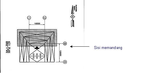
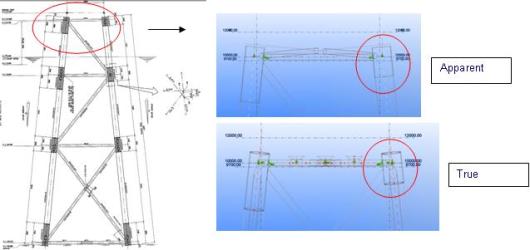
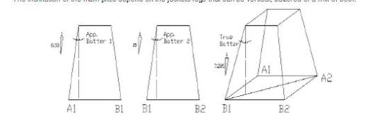
Didalam drawing jacket, jacket elevation setiap row, akan ada keterangan True Batter dan Apparent Batter. Keduanya mempunyai pengertian yang berbeda, dan perbedaannya terletak pada view atau sudut pandang. Apparent batter adalah kondisi jacket ketika ditidurin atau dibaringin, sehingga ukuran jacket sebenarnya adalah pada saat apparent batter. Apparent batter biasanya digunakan pada kaki yang miring. Sedangkan  true batter itu dilihat dari view/posisis arah memandang, sehingga kalo kita melihat arah X, ukurannya tidaklah 2D (Dimensi). Untuk lebih mengerti, dapat dilihat gambar dibawah ini.
Pada Row A, dikatakan bisa Apparent Batter dan True Batter karena kondisinya lurus.Sedangkan pada ROW B adalah ukuran Apparent Batter yang mejadi ukuran sebenarnya jacket pada ROW B. Jika, kita mengacu pada true Batter dan melihat view dari arah depan, maka pada ROW B ukurannya beda. Hal ini dikarenakan ROW B mempunyai kemiringan……
Apparent Batter Row B dalam kondisi dilihat 2D
Karena row B mempunyai kemiringan maka sangat kelihatan true dan apparentnya. Gambar dibawah ini bisa memperjelas lagi antara keduanya.
semoga bermanfaat.(ad)

Sunday, February 20, 2011

Foam Drilling

Hmm..Udah lama ga posting yang berbau ilmiah, akhir akhir ini malah sering ngebacot ga jelas. hahaha...

okelah, disini gw pengen ngebahas salah satu topik favorit gw, Drilling. Disini gw pengen ngebahas salah satu metode pemboran yang merupakan anggota Controlled Pressure Drilling, Underbalance Drilling, tapi lebih spesifik lagi, gw mau bahas salah satu bagian di UBD itu, Foam Drilling.

Foam merupakan komposisi dari gelembung-gelembung gas yang seragam tersebar di dalam fasa cairan yang kontinyu. Foam mengandung air, surfactant (surface active agent) sebagai foaming agent dan udara. Larutan cairan yaitu air dan surface active agent ditetapkan sebagai fasa yang kontinyu, dengan udara dinyatakan sebagai gelembung-gelembung gas yang diskontinyu. Pada sisi lain, mist didefinisikan sebagai fluida yang mengandung komponen-komponen yang identik, udara merupakan fasa kontinyu dan larutam cairan dinyatakan sebagai tetesan-tetesan diskontinyu.

Dalam operasi pemboran, gas-gas lain seperti nitrogen, natural gas, karbon dioksida dan inert gas yang dihasilkan dari buangan mesin terkadang digunakan sebagai pengganti udara. Karbon dioksida menghasilkan foam yang memiliki stabilitas yang jelek, karena ia memiliki daya larut tinggi dan sangat reaktif. Additive seperti polymer, graphite dan asphalt dapat ditambahkan dalam larutan foam karena dibutuhkan sebagai bahan stabilizer, corrosion inhibitor, shale inhibitor, dan pelumas. Akan tetapi banyak terbentuk (misalnya dihasilkan tanpa kontaminan padatan dan cairan yang secara alami didapatkan di dalam sumur) stable foam drilling dan operasi clean out dilakukan dengan suatu foamer dan air yang sederhana.

Foam mungkin dapat pula dihasilkan pada titik injeksi yang mana dikenal sebagai in-situ generation, atau dengan melewatkan berbagai komponen fluida melalui media porous ataupun coiled tubing generator.

Foam mempunyai karakteristik pengangkatan cutting yang baik oleh karena viskositasnya. Cutting-cutting dapat digantungkan dalam periode yang lama setelah sirkulasi dihentikan. Viskositas foam dapat menjadi tinggi bahkan di atas viskositas gas atau cairannya sendiri, namun densitasnya biasanya setengah lebih kecil dari densitas air. Dengan sifat-sifat tersebut maka foam lebih baik dalam menahan serpih-serpih pemboran, di samping itu slip velocitynya kecil, sehingga injeksinya juga akan berkurang.


Sistim foam dapat membantu meminimalkan problem dalam sistim sirkulasi yang menggunakan water maupun nitrogen. Problem hole cleaning dapat diminimalkan, karena sistim foam memiliki sifat-sifat yang lebih baik dalam menahan dan mentransport cutting. Segregasi fluida di annular dapat diminimalkan, karena sistim foam membantu untuk menjaga fasa liquid dalam suspensi, mencegah cairan dalam mebentuk slug yang besar pada dasar sumur. Hole drag juga dapat diminimalkan, karena foam memberikan tambahan sifat pelumasan dan juga menjaga gas dalam larutan foam, sepanjang bagian lateal. Akan tetapi, stable foam harus dapat dijaga pada tekanan dan temperatur dasar sumur. Sistim foan tidak hanya mengangkat cutting dari lubang bor lebih efisien, namun ia juga memiliki kemampuan untuk menahan cutting dalan larutan suspensi saat sirkulasi dihentikan.

Volume gas dan cairan, tekanan injeksi serta annulus back pressure harus dikontrol sewaktu mengaplikasikan foam dalam operasi pemboran. Foam harus dapat mengangkat padatan dan cairan di dalam lubang bor tanpa dengan breaking down menjadi aliran air dan slug yang sederhana atau tanpa mengikis dinding lubang bor (karena melebihi kecepatan aliran). Kapasitas pengangkatan fluida merupakan fungsi dari kecepatan alirannya, densitas dan reologinya. Volume dan tekanan injeksi yang dibutuhkan untuk pemboran secara ekonomi adalah merupakan fungsi dari kapasitas pengangkatan cutting. Pemahaman yang jelas tentang reologi foam dan mekanisme pengangkatan padatan ataupun cairan adalah penting untuk memprediksi barbagai parameter selama foam drilling.

Kehilangan friksi yang disebabkan oleh karena fasa padatan dan settling velocity dari setiap padatan harus dapat dihitung untuk memprediksi minimum volume udara dan cairan yang diperlukan secara akurat selama operasi foam drilling. Persamaan baru yang menggunakan kompresibilitas foam diperlukan untuk menghitung kehilangan tekanan (pressure drop) yang melalui bit.

Drilling foam yang baik mirip seperti cream. Ini diharapkan bahwa drilling foam harus mampu mengangkat cutting dari lubang bor, pada kecepatan annular yang sama. Suatu faktor angka yang mempengaruhi pada pembersihan lubang sumur oleh foam sangat sulit untuk dilakukan model. Pertama, reologi foam yang komplek dan sangat tergantung pada kualitas foam. Viskositas foam yang mengalir di dalam sumur lebih besar dibandingkan dengan dry gas atau mist sebagai fluida pemboran. Seperti terlihat sebelumnya, fraksi volume gas di dalam lightened drilling fluid, dan dengan definisi foam, kualitas foam, sangat kuat tergantung pada tekanan. Ada interaksi yang dipertimbangkan antara reologi dan tekanan sirkulasi. Keadaan itu selanjutnya dipersulit oleh aliran fluida formasi. Aliran gas akan meningkatkan kualitas, sedangkan aliran liquid akan menurunkan kualitas foam. Penurunan kualitas foam akan menyebabkan kehilangan viskositas dan akhirnya akan meningkatkan densitas foam.

Begitulah seklumit tentang foam drilling, yang mau tau tentangfoam drilling lebih dalam, bs cek link dibawah:


Air Drilling Association

Foam Drilling
Tundra Drilling Foam